M&E Consultants was engaged by Natural Resources Conservation Service to prepare the detailed design for the rehabilitation of Olmitos and Garcias Creek Floodwater Retarding Structure (FRS) No. 7. Site 7 is a single-purpose, low hazard dam designed and constructed in 1963 for flood prevention and sediment retention. The structure is an integral part of the Olmitos and Garcias Creek Watershed Plan approved for operation in June 1960 under the authority of Public Law 83-566 and as supplemented under Public Laws 83-566 for rehabilitation.
FRS No. 7 is an existing floodwater retarding structure located approximately 6 miles east of Rio Grande City, Starr County, Texas. The site is situated within the Gulf Costal Plains Physiographic Area of Texas and is located on Olmitos Creek, which flows into the Rio Grande. It was constructed by the Soil Conservation Service (now Natural Resources Conservation Service) cooperating with the Starr County Soil and Water Conservation District and Starr County Commissioners Court as a single-purpose, low hazard, floodwater retarding structure located in a predominantly agricultural area. Development downstream of the dam has occurred, resulting in the need to change the hazard class from low to high. A supplemental watershed plan was developed in June 2012 to address rehabilitating Site 7 to meet current design, performance, and safety standards required for high hazard structures.
The work plan selected rehabilitation alternative consists of raising the top of dam elevation approximately 4 feet to elevation 203.1; installing an additional 30-inch principal spillway pipe consisting of a hooded inlet and an impact basin at the outlet end; widening the auxiliary spillway from 200 feet to 300 feet and lowering the crest by 2.2 feet; and armoring the auxiliary spillway with soil cement.
M&E Consultants performed a review of the work plan selected alternative and had reservation that armoring the auxiliary spillway with the proposed 6-inch layer of soil cement would be effective. The soil cement armoring was proposed because the soil materials in the auxiliary spillway will not meet the stability and integrity requirements of TR-60. The anticipated velocities for the freeboard hydrograph are in excess of 35 feet per second (fps). Soil cement varies in strength because of the in-situ materials used to produce the product are not consistent. Cracking will occur, creating small concrete blocks that could potential be removed by the hydraulic forces.
Two alternatives to soil cement armoring were analyzed for the auxiliary spillway. The first alternative consisted of a roller compacted concrete (RCC) grade control structure at the existing crest section and another at the existing auxiliary spillway’s curve termination and the placement of a 1-foot thick layer of soil cement between the structures.
The second alternative analyzed consisted of the construction of a RCC stepped chute structure at the curve termination and re-grading the inlet above the structure. The cost for both alternatives are comparable, but the RCC stepped chute provided more stability and therefore was chosen for the design.
A review of the planning hydrology model discovered a data entry error for the rainfall value used for the principal spillway routing and the principal spillway elevation was not adjusted to the new datum. The correct rainfall value and adjusted elevation resulted in lowering the auxiliary spillway 0.8 feet.
A review of the principal spillway hydrograph (PSH) routing showed that the 10-day drawdown requirement was not achieved because the discharge calculations for the existing 30-inch principal spillway and the planned 30-inch hooded inlet principal spillway were in error. The 10-day drawdown requirement can be achieved with the installation of a 42-inch principal spillway system.
As a result of the M&E Consultants’ review, the work plan selected alternative will be changed as follows:
- The existing 30-inch principal spillway and planned 30-inch hooded inlet principal spillway systems will be replaced with a single 42-inch principal spillway system.
- The soil cement armoring of the auxiliary spillway will be replace with a RCC stepped chute spillway.
- The elevation of the principal spillway will be changed to elevation 170.2 MSL.
- The elevation and width of the auxiliary spillway will be changed to elevation 190.8 MSL and a width of 270 ft.
The planning and design survey was performed in October 2011 by M&E Consultants. M&E Consultants performed an additional survey in May 2014 to gather more detailed information for the design. The survey was performed using North American Datum of 1983 (NAD83) and North American Vertical Datum of 1988 (NAVD88). GPS survey instrument calibrated to the State Plane Coordinate System (SPCS) was employed for the survey. Starr County is in the South Zone of the SPCS. The GPS data was processed using Online Positioning User Service (OPUS). OPUS processes GPS data files with the same models and tools which help manage the nation’s Continuously Operating Reference Station (CORS) network, resulting in highly accurate and consistent coordinates that can be utilized among varying project stakeholders. The level of survey performed exceeds the minimum required by NRCS for the type of construction to be performed.
-
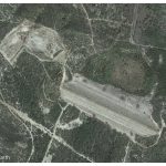
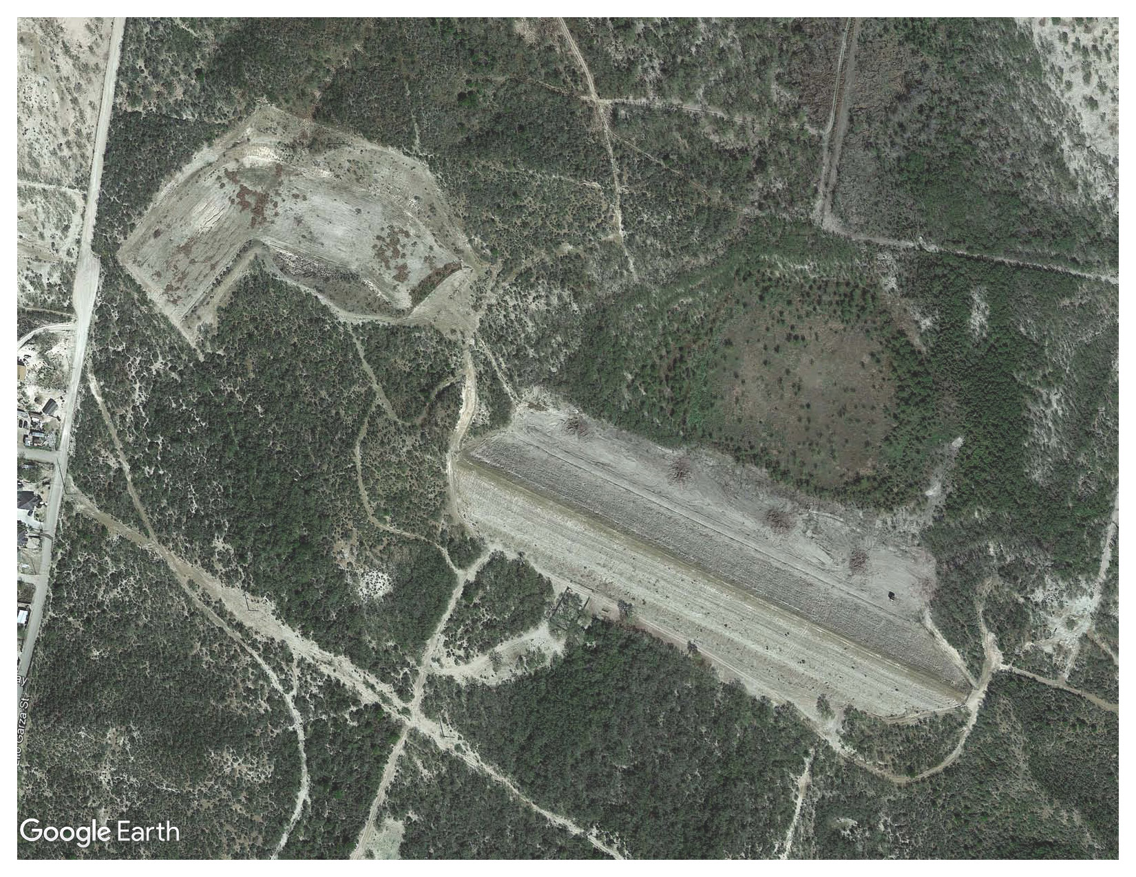
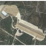
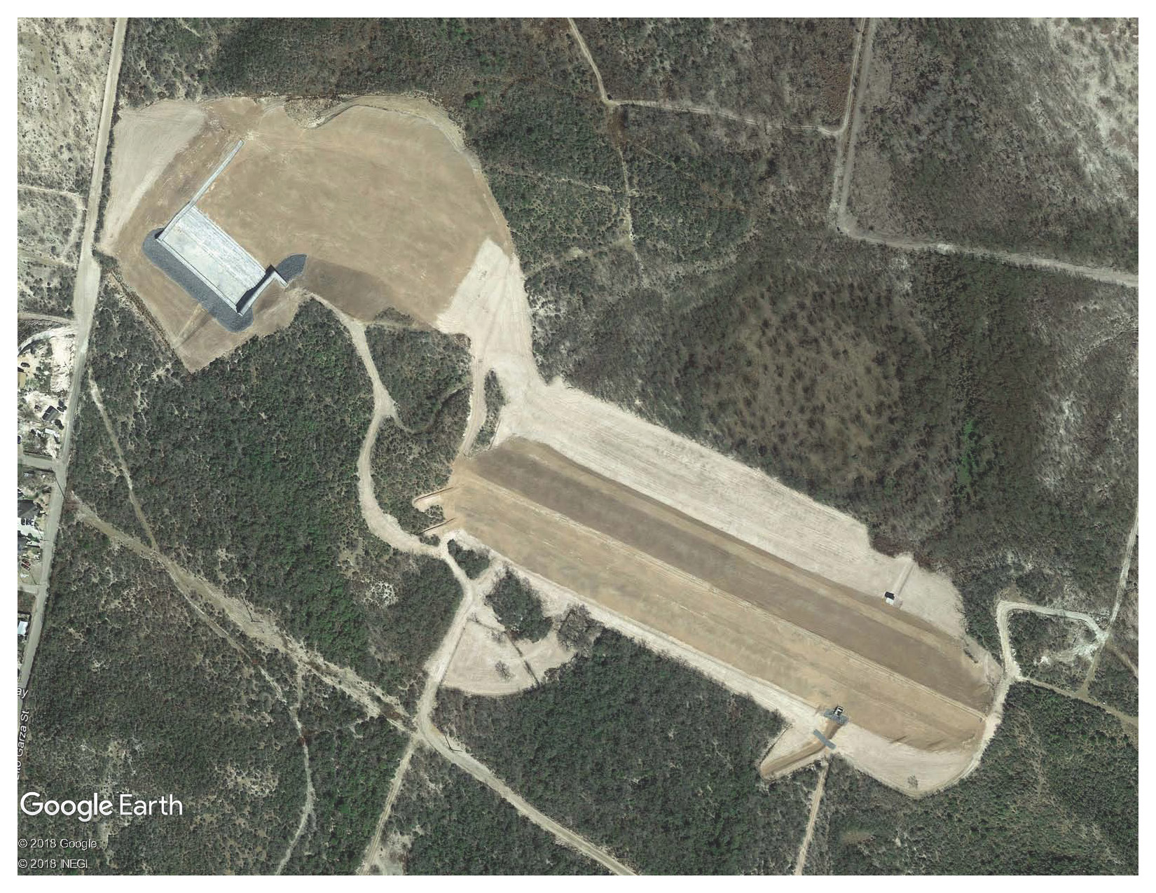
- Overview of Existing Site
-
- Overview of Rehabilitated Site
-
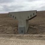
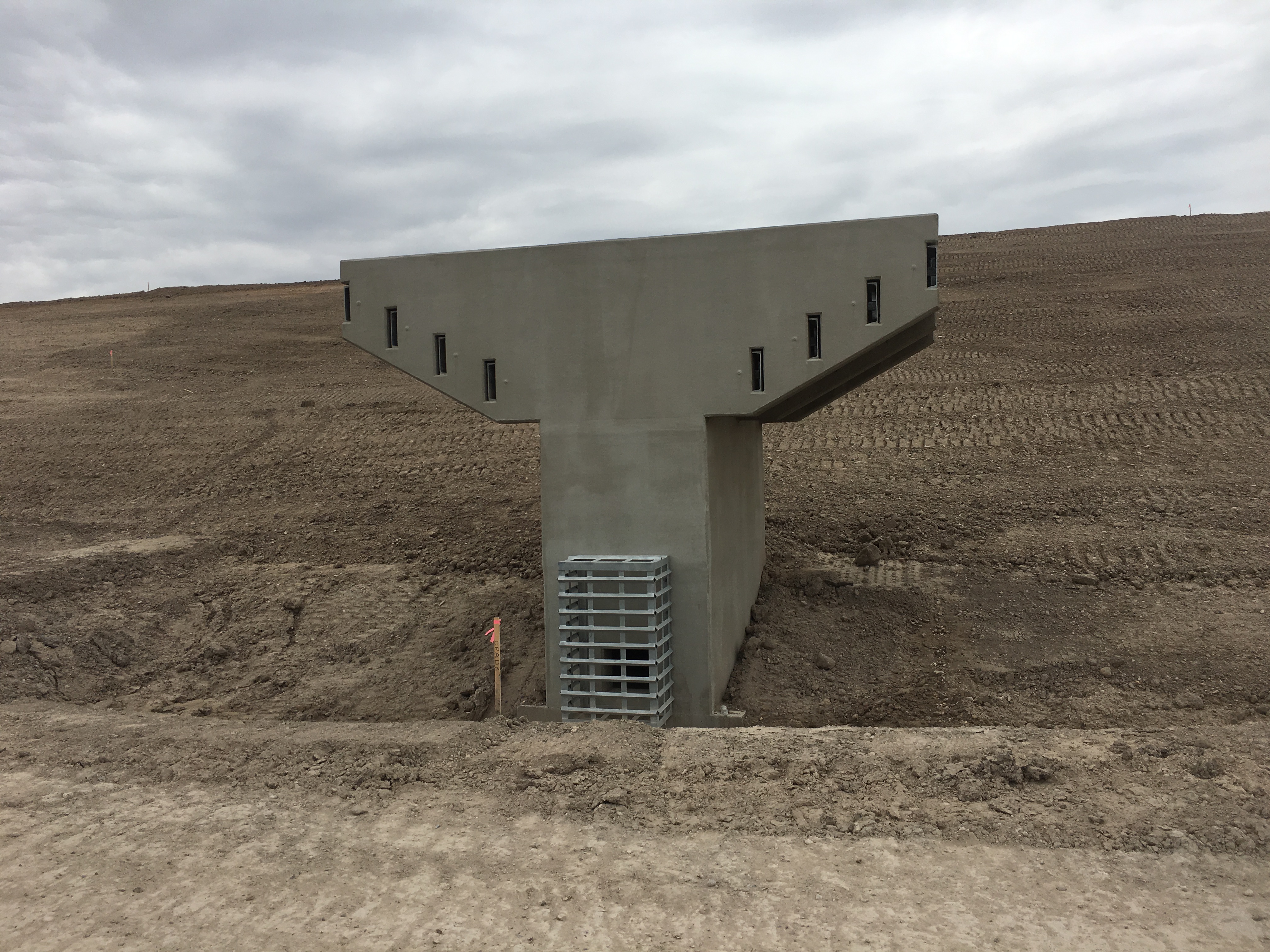
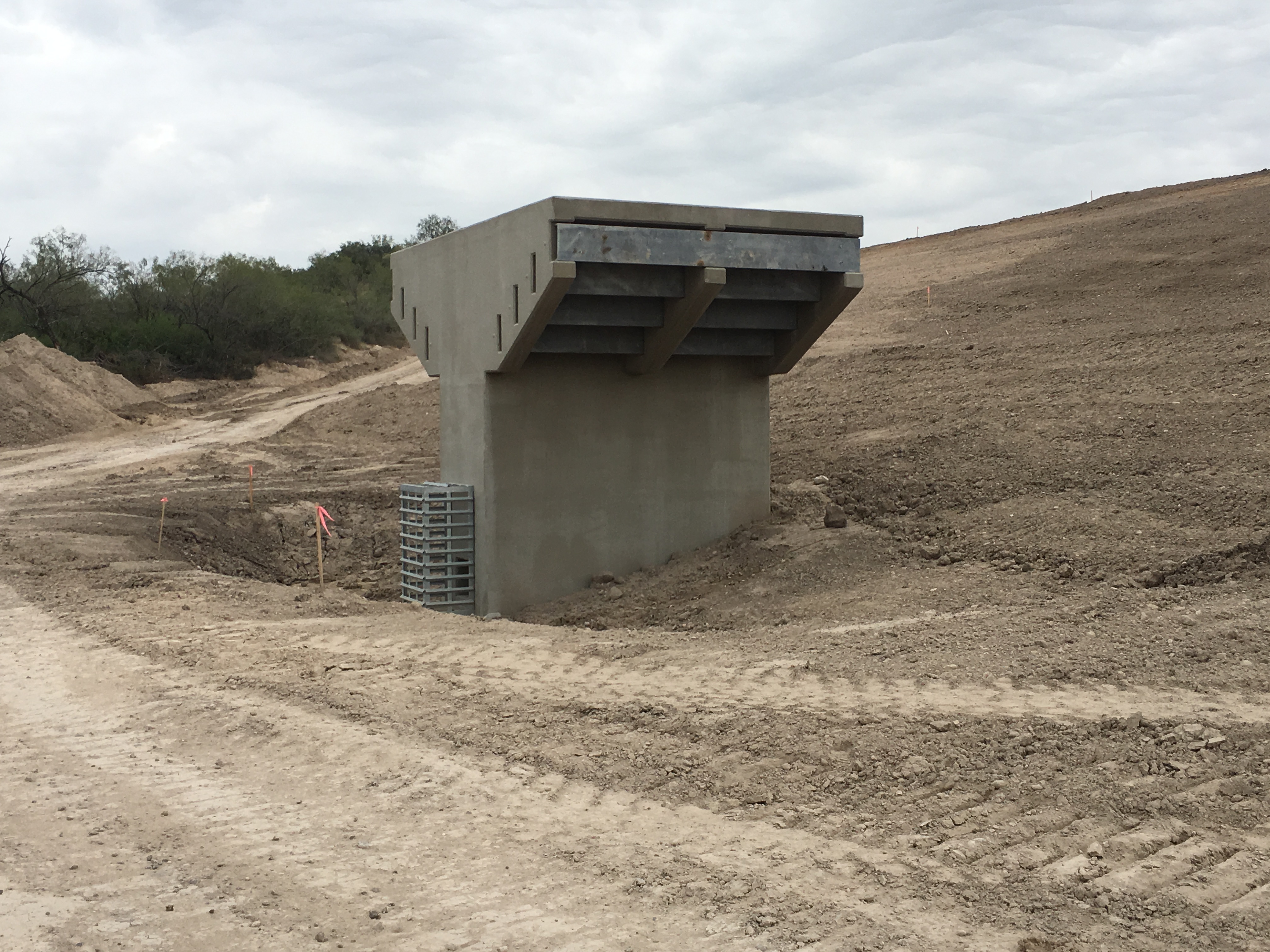
- Completed Principal Spillway Inlet Tower
-
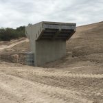
- Completed Principal Spillway Inlet Tower
-
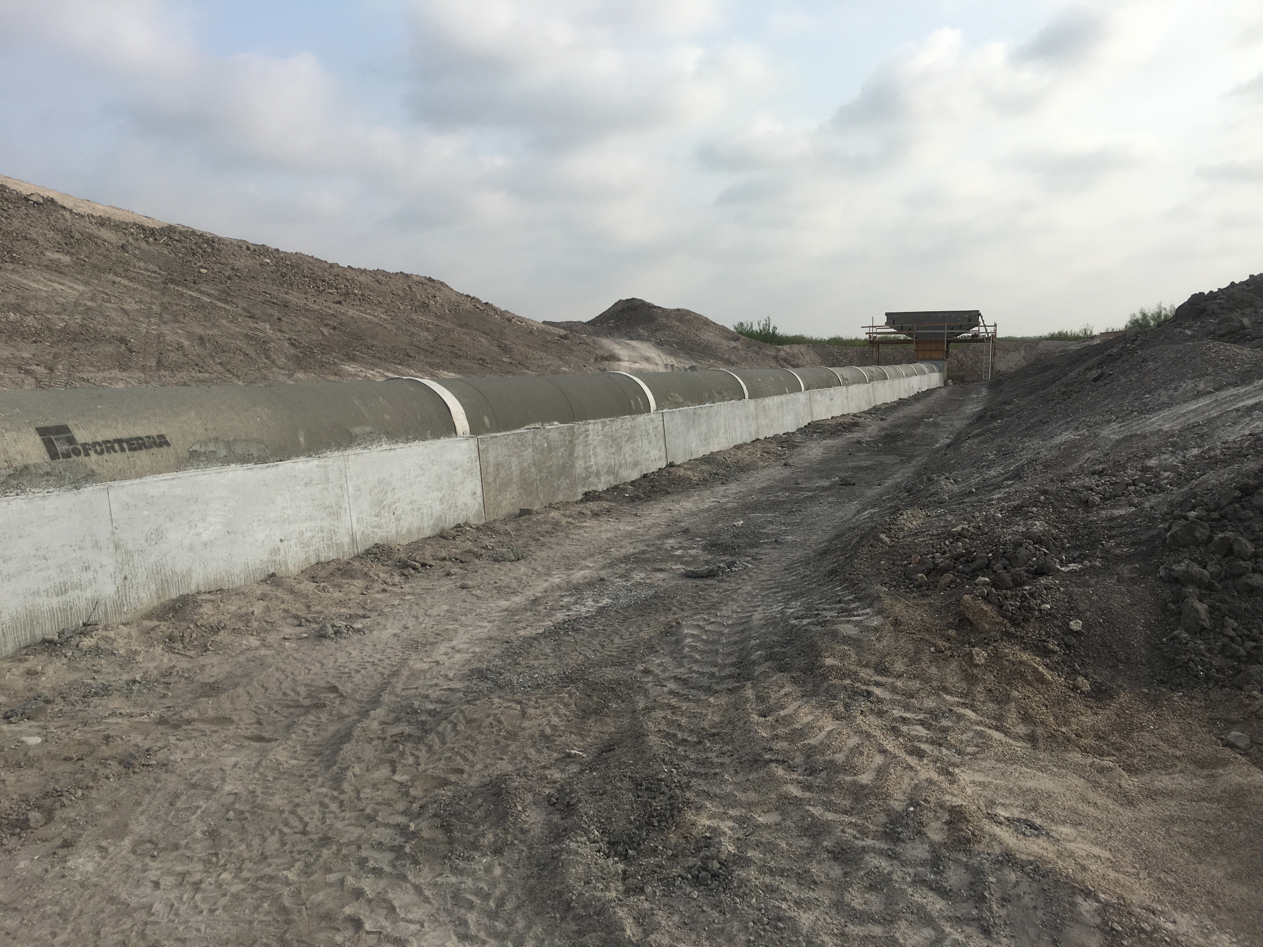
- Construction of Principal Spillway Impact Basin
-
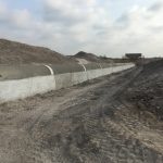
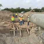
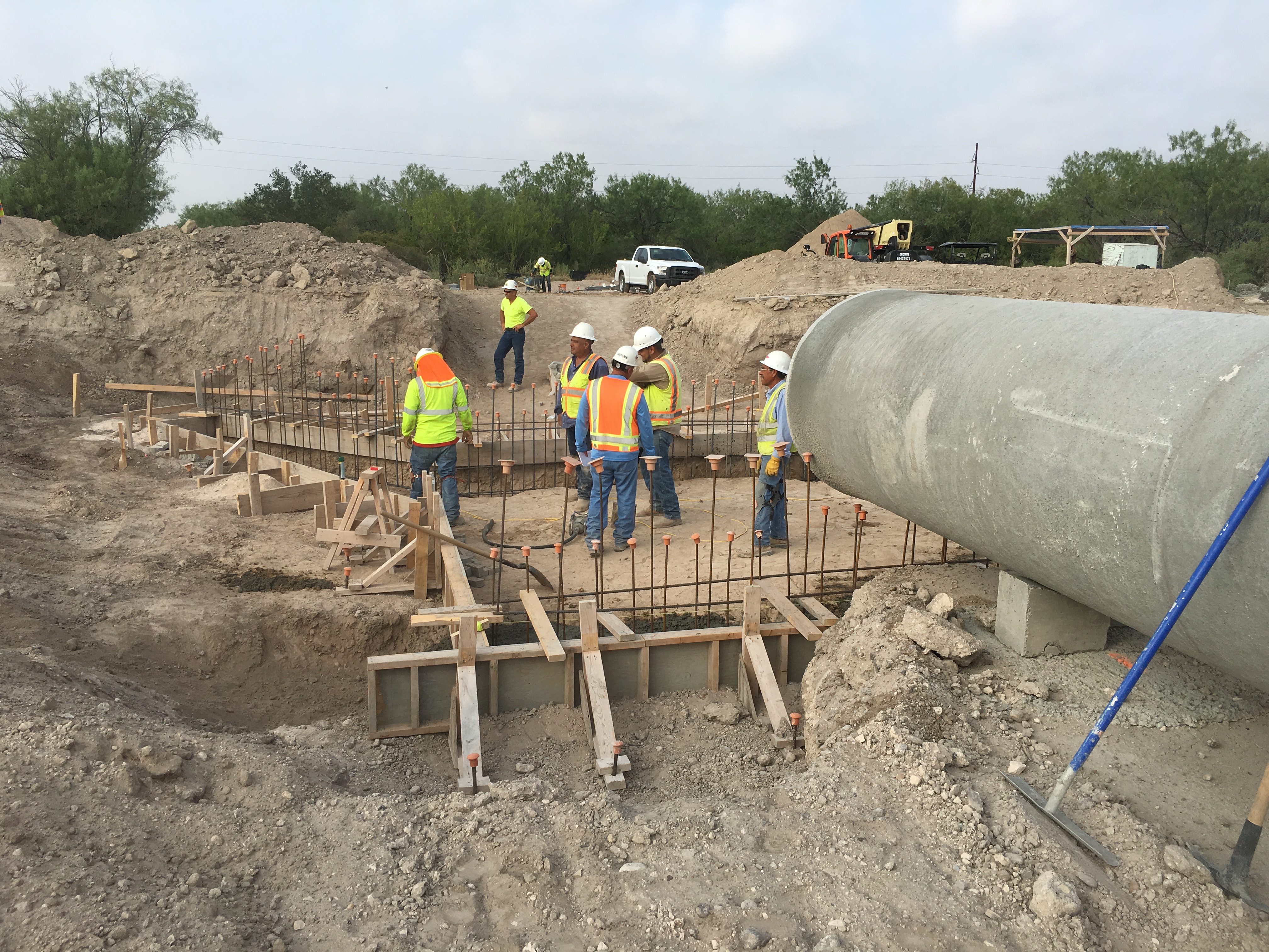
- Construction of Principal Spillway Inlet Tower and Conduit
-
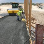
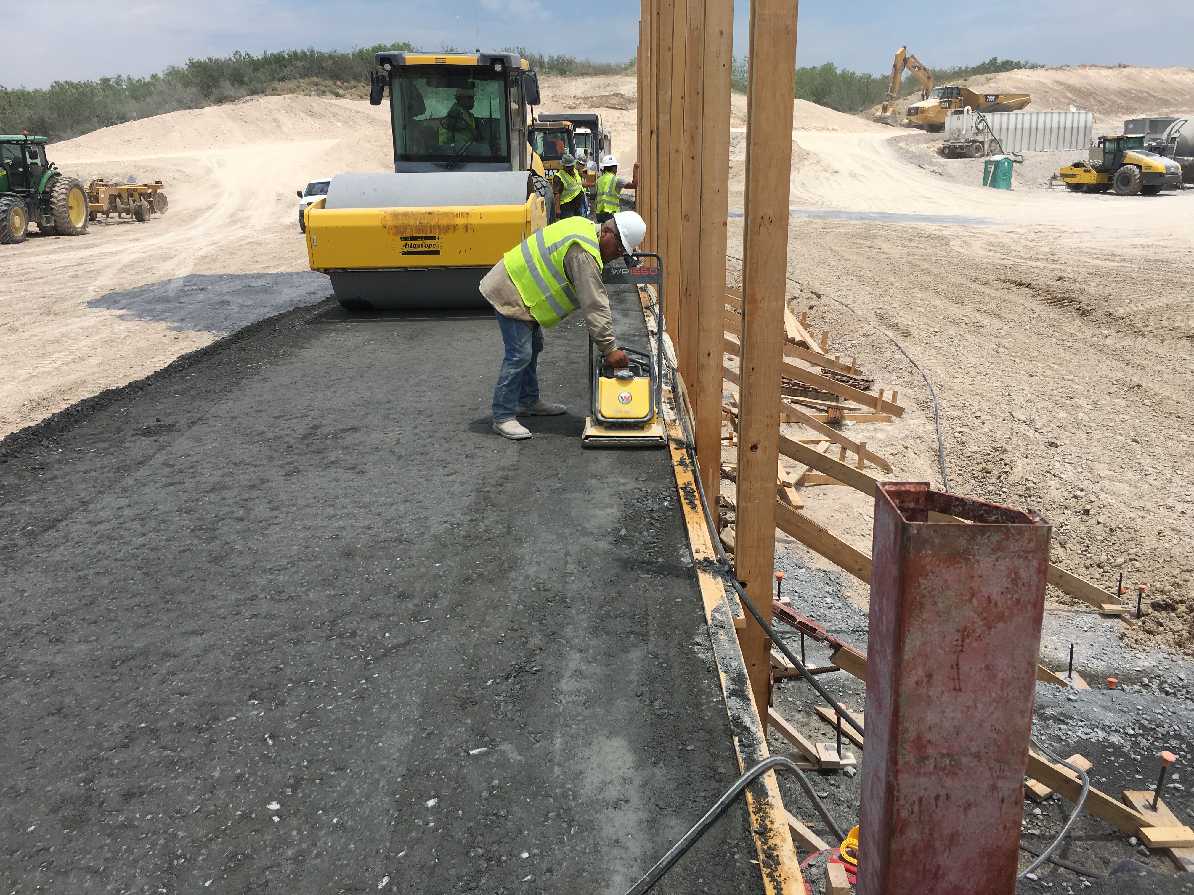
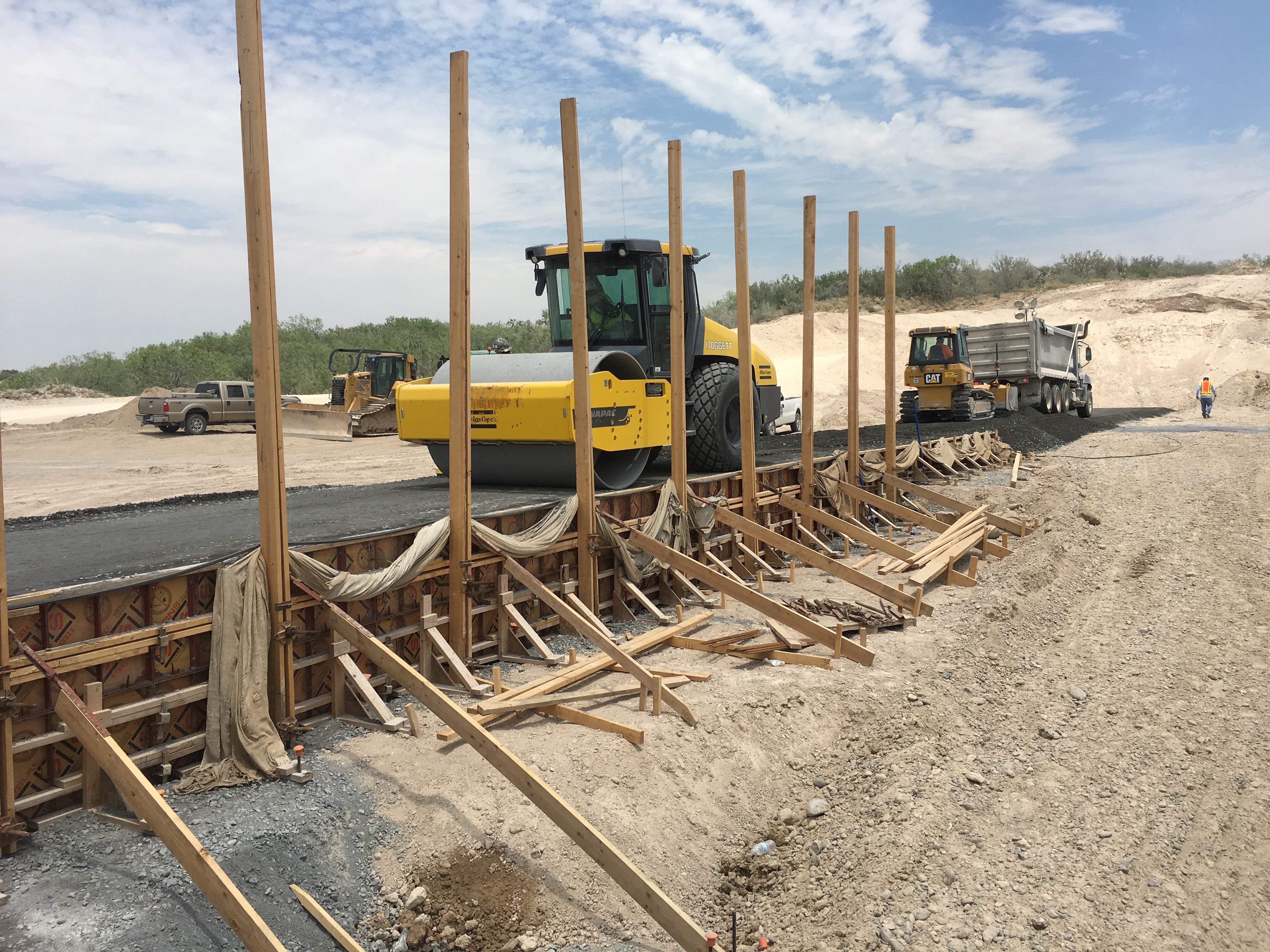
- Construction of RCC Lifts
-
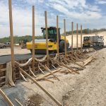
- Construction of RCC Lifts
-
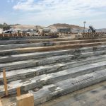
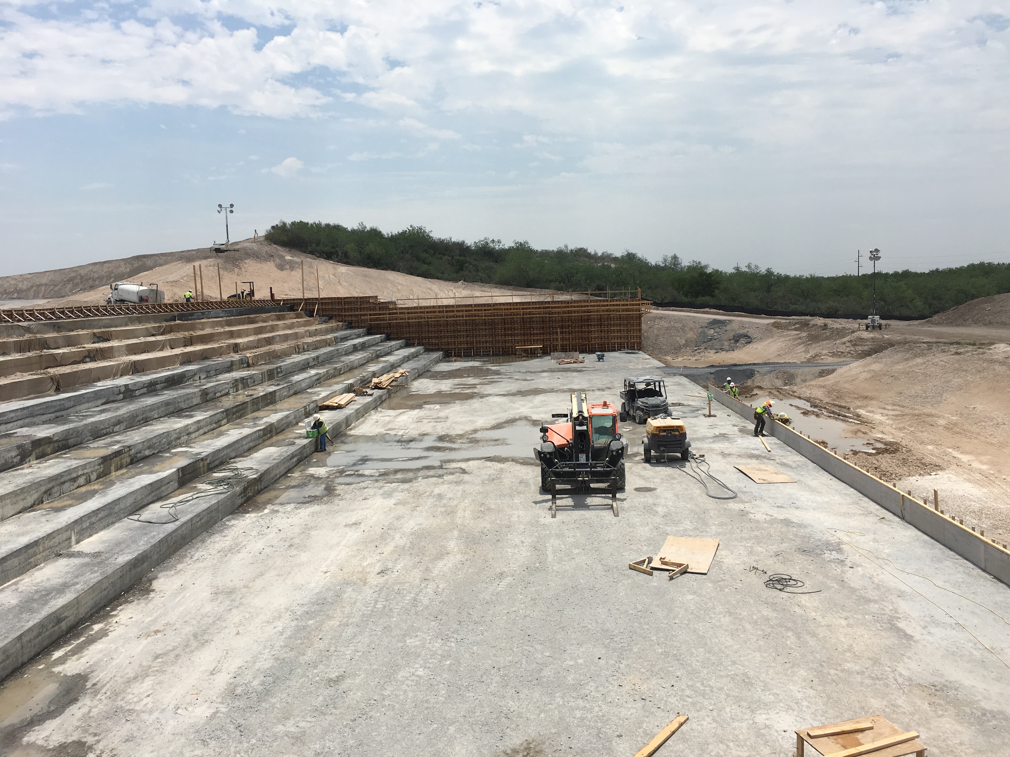
- Construction of RCC Auxiliary Spillway Steps
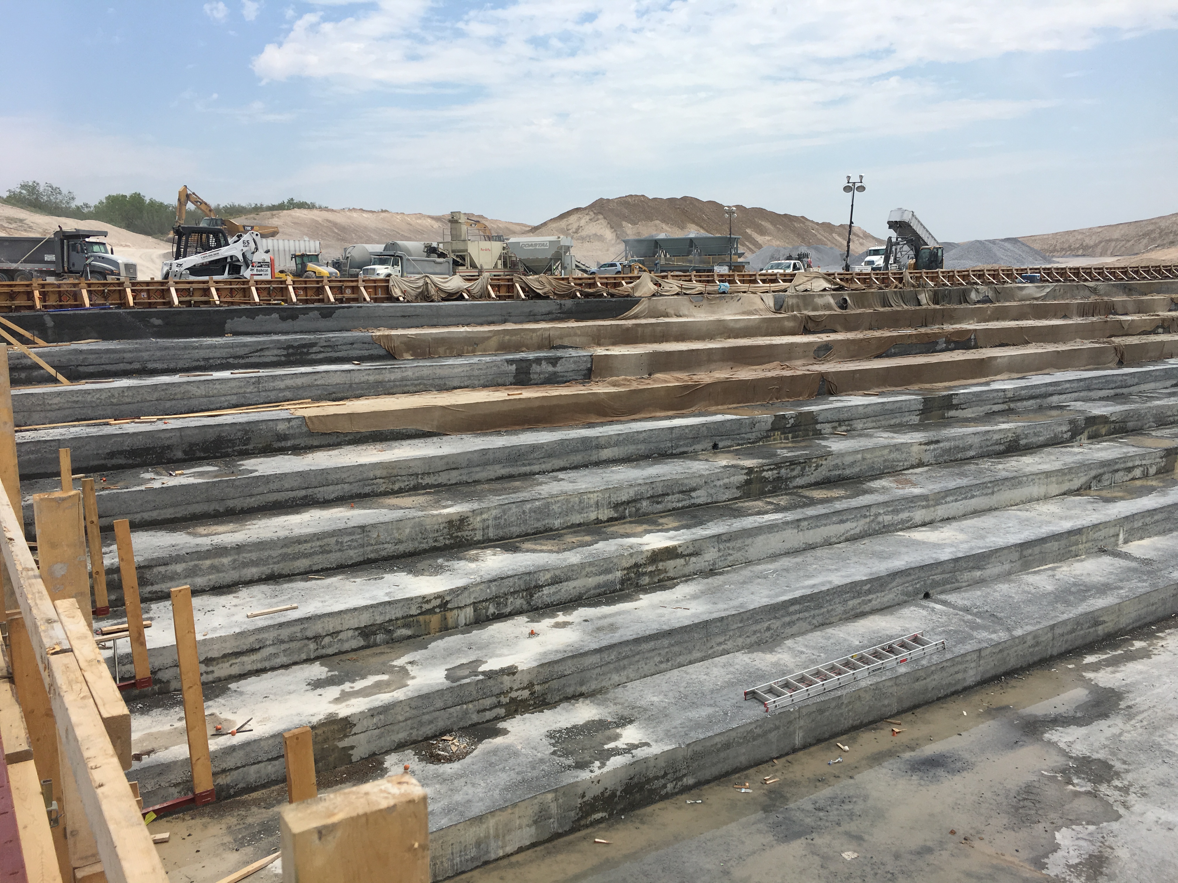
-
- Construction of RCC Auxiliary Spillway Side Walls
-
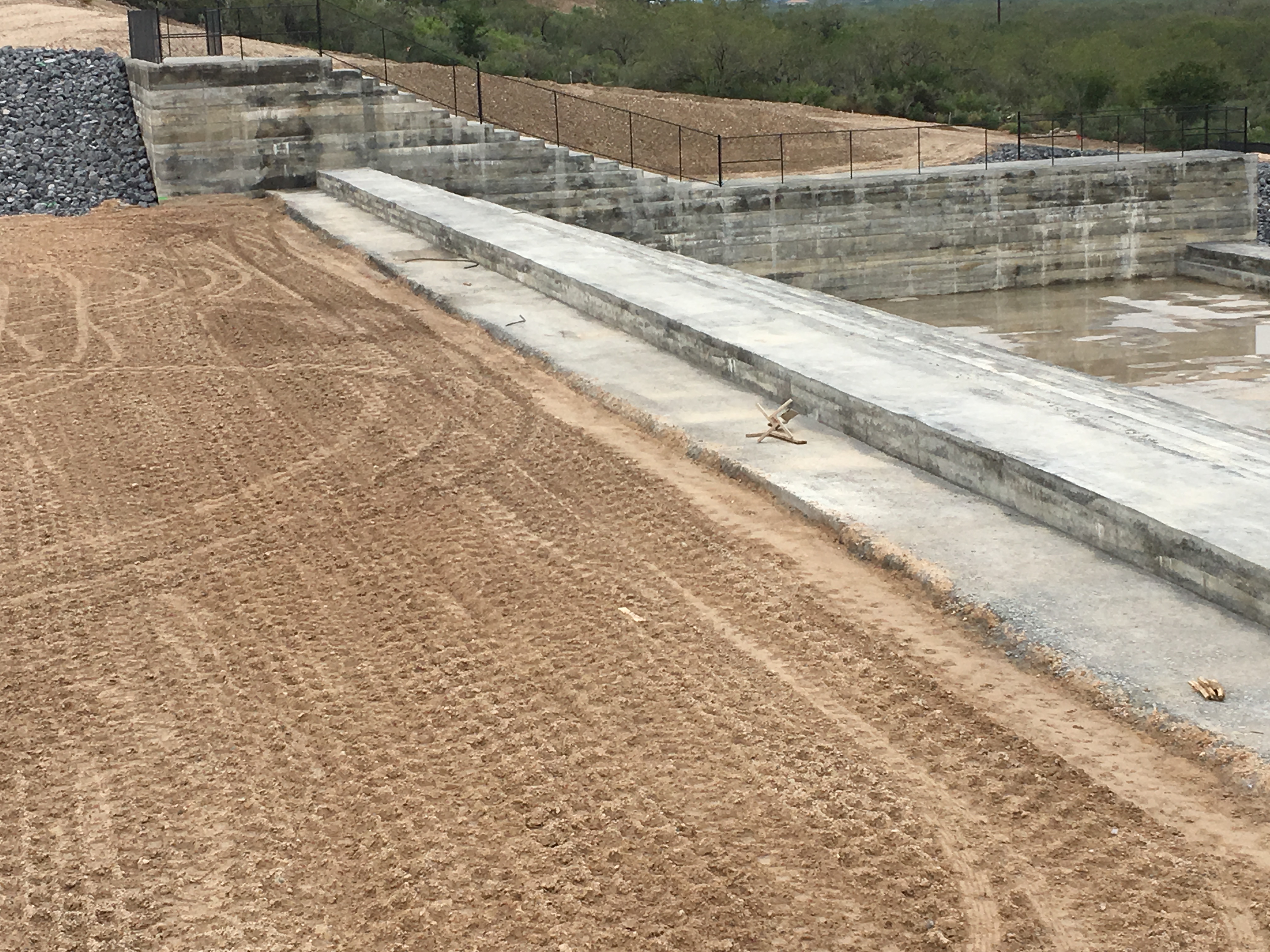
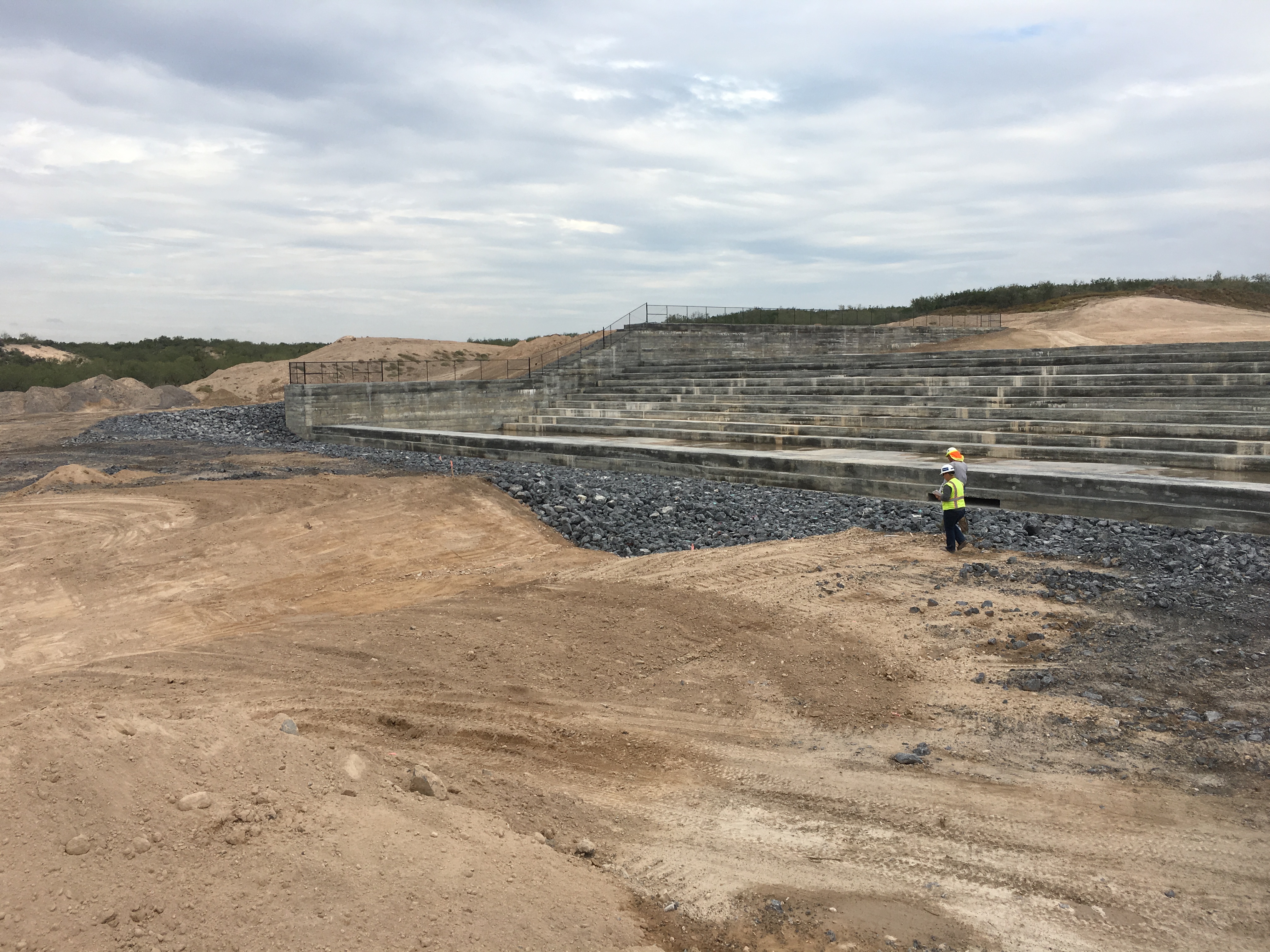
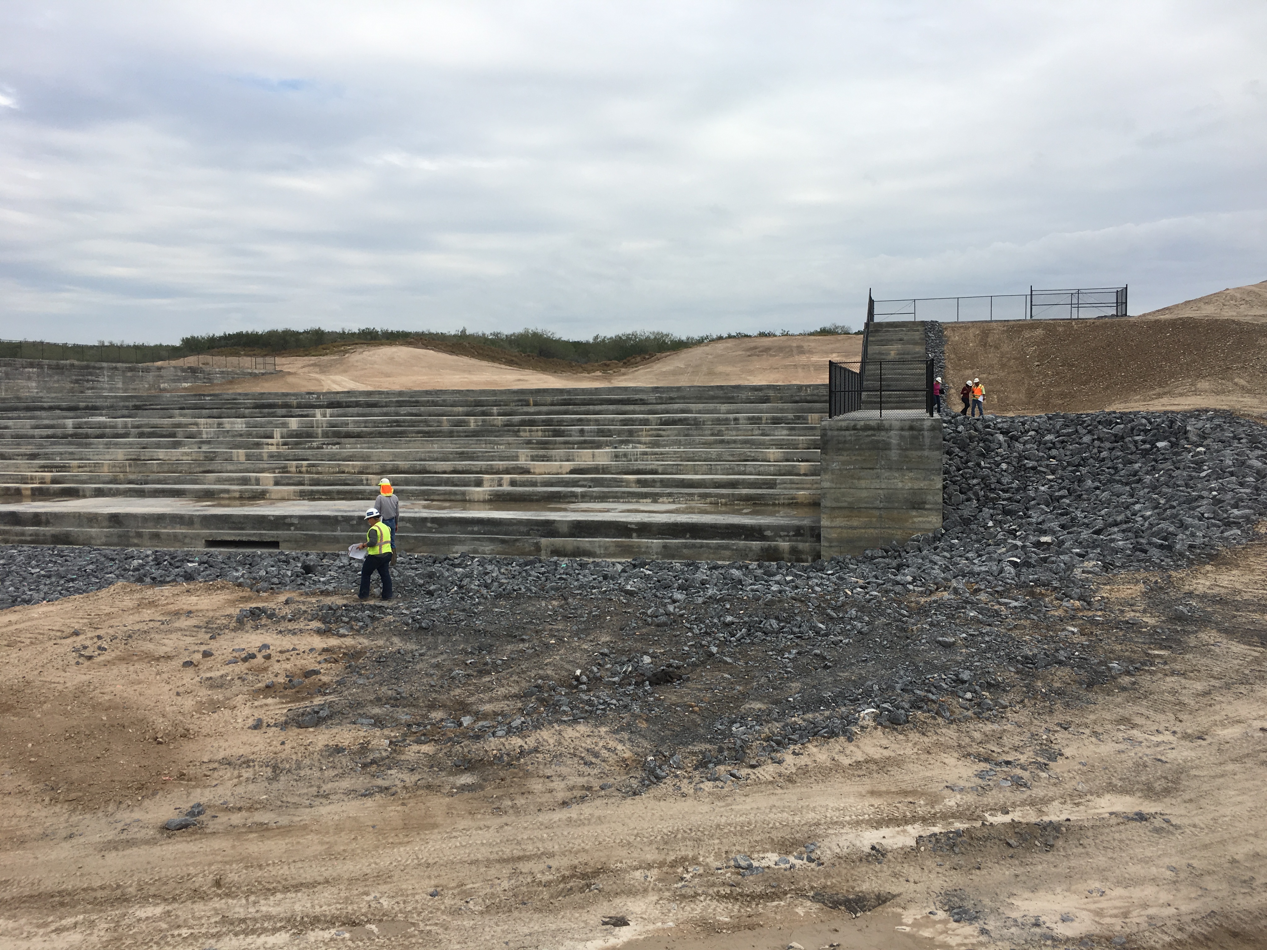
- Completed RCC Auxiliary Spillway
-
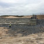
- Completed RCC Auxiliary Spillway
-
- Completed RCC Auxiliary Spillway Stilling Basin
-
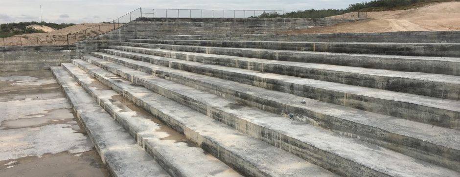
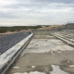
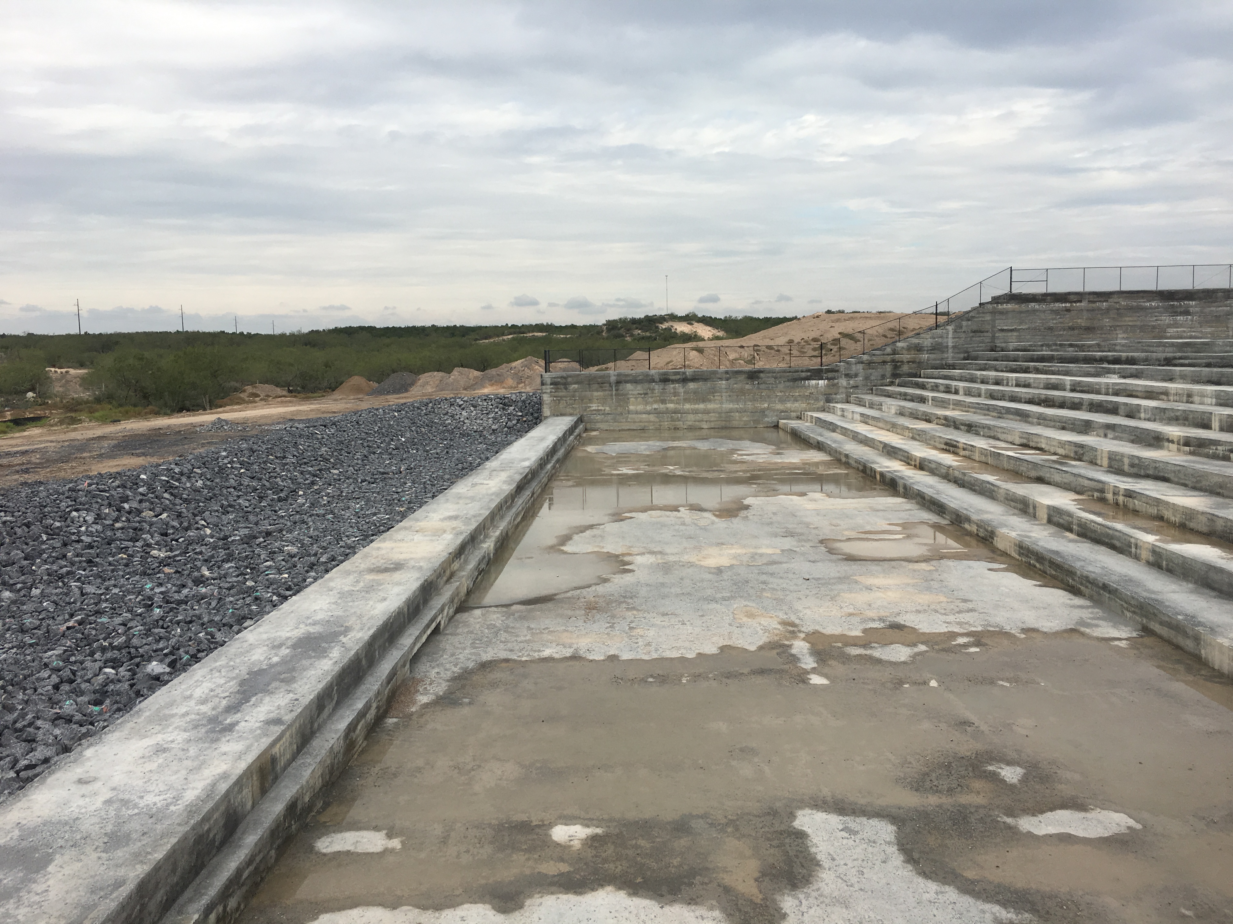
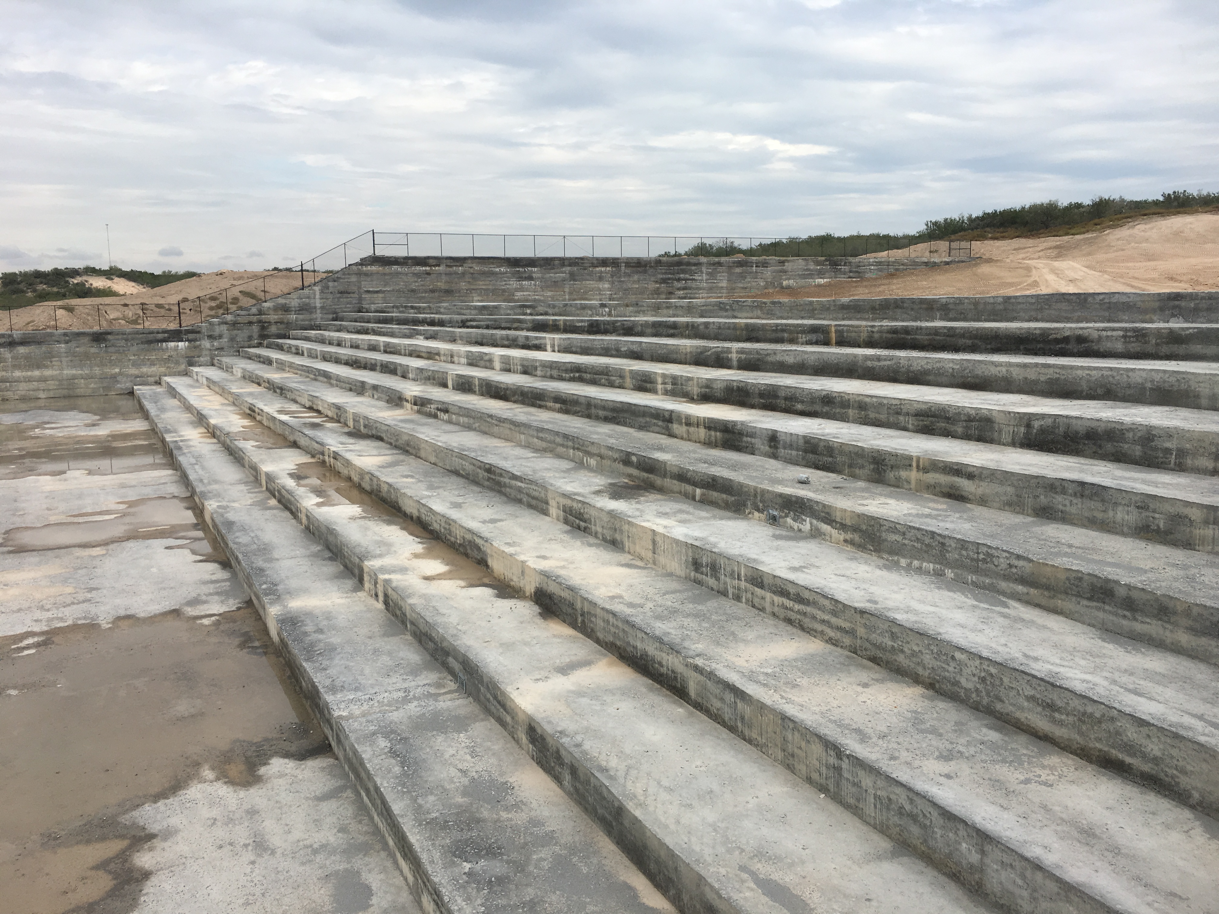
- Completed RCC Auxiliary Spillway Steps
-
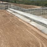
- Completed RCC Auxiliary Spillway Crest